By James Loper, P.E., PMP
The U.S. Navy’s submarine weapon systems, intended to serve as an undetectable defense and launch method, are designed specifically for stealth and precise delivery of torpedoes, missiles, and sensing equipment. Testing and evaluating these launch systems is critical in achieving and maintaining mission readiness. Traditionally, they are tested in open water, but this requires retrieving test vehicles from the sea floor.
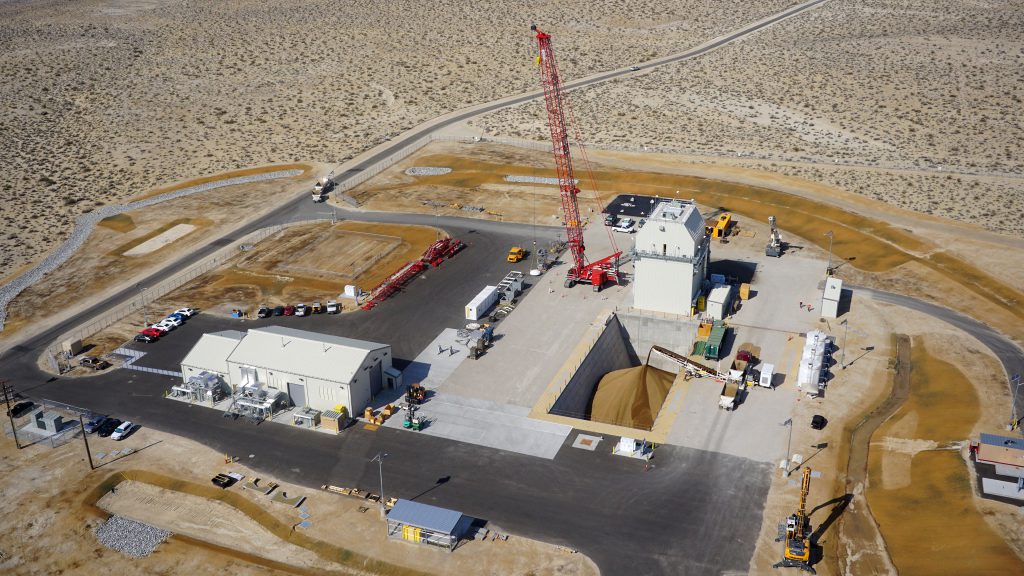
To address this, the Navy engaged with Jacobs to design a full-scale, land-based Launch Test Complex in the western Mojave Desert at Naval Air Weapons Station China Lake, Calif. This first of its kind facility represents the next generation of launcher testing systems and aligns with the Navy’s commitment to environmental sustainability.
The goal of the Launch Test Complex is to ensure that the launcher defense system is adequately tested in a reliable and safe manner. To do so required the design and construction of an Earth-Based Arrestment Box (EBAB)—a structured pit capable of catching and withstanding the impact from a 130,000-lb launch test vehicle traveling at speeds greater than 80-mph.
Not only did the floors and walls of the EBAB have to withstand the significant forces of the tests, but it needed to meet high resilience and environmental sustainability standards.

SUSTAINABLE DESIGN SOLUTION
The EBAB is a slotted box, 43-ft deep by 145-ft long, with inclined sidewalls and filled with pea gravel. At floor level it is 30-ft wide and 60-ft wide. During operation, the EBAB is responsible for catching the launch test vehicles that are fired from the overhead launch test stand at various trajectories. A critical program requirement was to be able to safely launch and reuse the same test vehicle for 60 launches during the planned 15-year test period. This requirement dictated that both the launcher structure and EBAB retain their form and function for the entire period without degradation.
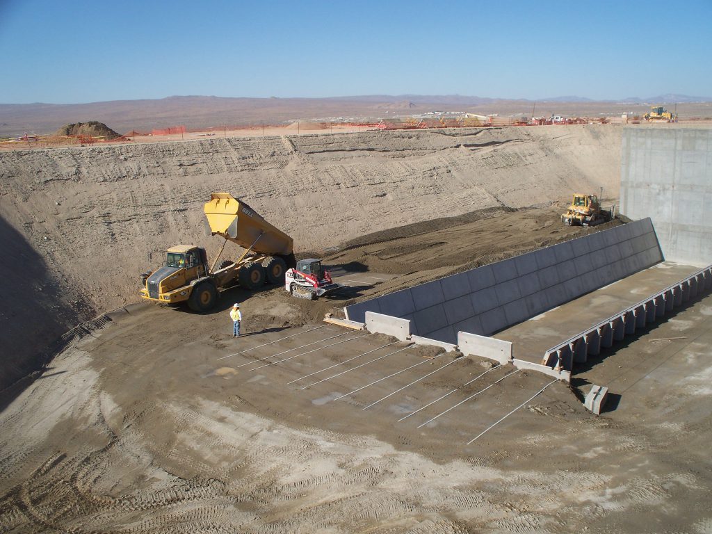
Constructable and Cost-Effective. From the onset, the project team strived to deliver a facility that would meet mission requirements while also leaving minimal impact on the desert environment. After initially considering massive concrete walls and floor for the EBAB as a “brute force” approach, a more constructible, cost-effective, and environmentally sustainable approach was developed. Instead of using cast-in-place concrete walls around the entire perimeter, mechanically stabilized earth was used for three of the four walls. This approach uses a series of reinforced precast concrete panels with metal straps embedded into the backfill. The design was further optimized by sloping these walls to create a slotted configuration, reducing the pea gravel required to fill the pit by 25 percent.
The amount of excavation and backfill required by the project was another important constructability and environmental concern. Based on subsurface sampling and testing, it was determined that soils present at the site were not adequate for usage as backfill. Rather than importing select materials, these onsite soils were mixed with cement to create a stiff substance that could support repeated impact loadings caused by the launch tests. The construction contractor coordinated the mixing and compacting of the soil/cement backfill with the mechanically stabilized earth wall panels and straps placement. This approach saved an enormous amount of labor and material, and significantly reduced the carbon footprint and land disturbance.
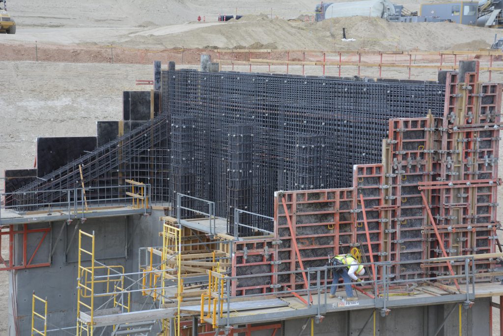
For the fourth wall of the EBAB, which would be adjacent to the launcher structure, additional design and construction considerations were necessary. The team went through an intensive computerized analysis of 72 landing conditions that considered vibrational and dynamic forces and fatigue stresses. The final design is a heavily reinforced wall and footing system comprised of wing walls at each end along with three intermediate ribs that are used to stiffen the wall. Construction required nearly 1,200-yd³ of cast-in-place concrete and 190-T of steel rebar.
Reducing Environmental Impact. Alongside meeting the heavy reinforcement needed for this wall, the team continued to focus on sustainability requirements throughout construction. In concrete building projects, a portion of the cement is often replaced with fly ash or another pozzolan to decrease the potential for thermal and shrinkage cracking. In this project, 50 percent of the cement was replaced with fly ash. That represents more than twice the amount commonly used.
This approach provided two essential benefits. First, the concrete reached the required 90-day compressive strength of 6,000-psi while exhibiting a negligible amount of cracking. Second, the use of high-volume fly ash concrete significantly reduced the project’s overall carbon footprint (fly ash is a fine powder that is a recycled byproduct of coal incineration).

of reducing the required land disturbance over cast-in-place concrete walls.
REDUCING BY REUSING
Steel reinforcing was another sustainability consideration applied on the structure. As is typical for most domestic projects, more than 95 percent of the material used in the rebars came from recycled scrap metal. To further reduce the carbon footprint, the size and number of rebars required was optimized by strategically accounting for stresses caused by operational and seismic loads.
The combined use of mechanically stabilized earth wall panels, soil cement, high-volume fly ash concrete, and optimized rebars demonstrates a commitment to sustainable and thoughtful designs that still meet mission requirements.

REFINEMENTS FOR THE FUTURE
The facility has been operational for several years, and in addition to successfully supporting testing loads, the launching structure and EBAB resisted a significant seismic event close to the site without damage. This project also has demonstrated that construction of densely reinforced, massive concrete walls and foundations using high-volume fly ash is feasible. Importantly, innovations developed through this project are being leveraged to better mitigate seismic hazards on several other testing facilities at China Lake currently under design and construction.
Additionally, Jacobs designed another launch test facility at a separate Navy installation that is yet more advanced. This next- generation facility features a 120-ft deep in-ground water tank and a system to simulate underwater current and cameras to evaluate future launcher systems better. Both the current and planned launch test facilities are well-positioned to support advanced testing for the Navy’s defense program in the future.
Related Posts
-

Designing for Resilience Against Coastal Hazards
Withstanding severe coastal weather and remaining operationally ready through climate hazards and extreme storms is becoming increasingly mission-essential for military installations as the intensity of these events increases. -

Navigating Challenges When Building Abroad
As U.S. strategic interests abroad evolve and require greater military construction investment, understanding the challenges and pitfalls that building abroad can pose is crucial in order to best control the cost and scheduling of a project. -

Creating SCIFs That Secure and Inspire
In designing secured spaces for federal agencies, the requirement for uncompromised security can also be balanced with human-centered design to create compartmentalized yet engaging environments that support both military and intelligence operations.


