By Jeremy Jones, Ph.D., P.E
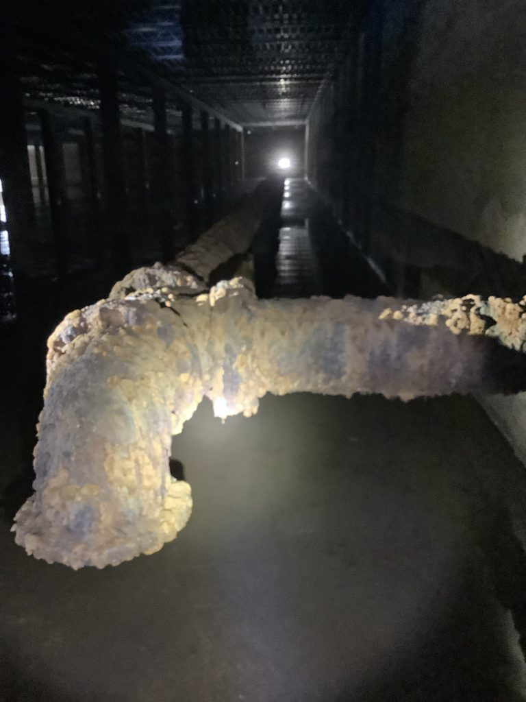
Increasingly, the U.S. Navy has understood that a water distribution system is a dynamic environment with a host of reactions occurring between the water and the pipe wall interior. Water reservoirs, tanks, and piping serve as a biological and chemical reactor, and these structures can be a primary factor in determining water residence times, disinfectant residual losses, and increased biofilm activity along the pipe wall.
Installations across the Hampton Roads region are serving as an example of the strategies
the U.S. Navy is employing to decrease
water residence times and preserve
water quality in distribution systems.
Water distribution systems on military installation have unique characteristics that can degrade water quality when compared to municipal distribution systems. Sporadic land development creates long runs of pipe with relatively low water usage, explosive arc requirements for ordnance areas further isolates buildings, and, on naval installations, elevated towers have flat hydraulic grade lines, as the sites are generally located in relatively flat coastal areas.
Fire protection requirements for nonresidential facilities have frequently resulted in oversized pipes and storage requirements, with the storage tanks initially constructed with little consideration for finished water quality. Additionally, distribution systems often contain significant sections of unlined cast iron, which provides efficient niches for biofilm growth to proliferate. As a result, water ages within military distribution grids are elevated compared to municipal systems with similar geographic boundaries.
Water consumption demands at installations can vary greatly due to fluctuating military populations, variable ship berthing movements, and water conservation efforts that have reduced water usage by 25 percent in the last fifteen years. These reductions in water consumption also contribute to longer detention times.
Facing these challenges, the Navy has employed a variety of corrective actions to preserve potable water quality in its distribution systems and reduce water residence times.
DISTRIBUTION CHALLENGES
For fire protection, the Navy follows guidance from the Unified Facilities Criteria, which mirrors the current criteria issued by the National Fire Protection Association. With many sprinklered facilities in an industrial storage setting, it is not unusual to have multiple buildings with sprinkler demands over 2,500-gal/min for 120-min. While the criterion is more specific, the general rule of thumb is to provide storage equal to the average daily demand plus the demand of the worst-case fire scenario.
With sporadic development and blast arc requirements, distribution systems are frequently segmented into isolated zones that are unable to share storage capacity. As a result, multiple reservoirs become necessary to serve independent water systems within the same installation.
These factors tend to make bases top heavy with respect to storage requirements. In the Hampton Roads region, the Navy manages each water system with the general premise of maintaining a residence time of less than five days. This ratio varies across the region, from Norfolk Naval Base (maintaining a ratio of 1.1) to Yorktown Naval Weapons Station (2.7), Oceana Naval Air Station (3.7), and Little Creek Joint Expeditionary Base (4.4).
Another challenge for water distribution systems is the fact that many installations still operate steam plants to provide for ship and heating purposes. As a result, the daily peak water demands usually occur in wintertime. In summer, water usage is lower when distribution disinfectant residuals can be more problematic to maintain. Decreasing residuals over the summer typically follow the same pattern as the surrounding municipalities.
REDUCING WATER AGE
This strategy was employed at Little Creek Joint Expeditionary Base, where the tank fill line discharges above the water level
and the bottom suction line feeds the
station pumps for a
1-million-gal ground level reservoir.
To reduce water age in distribution systems, the Navy realized that a complete array of options was necessary to accommodate each installation.
Circular Ground Level Reservoirs. When construction projects allow for tank piping to be renovated, engineers look to evaluate the tank to provide as much mixing as possible during the filling operation. This strategy was employed at Little Creek Joint Expeditionary Base, where the tank fill line discharges above the water level and the bottom suction line feeds the station pumps for a 1-million- gal ground level reservoir.
Reducing the tank fill levels in response to lower distribution demands also provides some flexibility in minimizing water age. Because there is limited steam production in summer, the average daily water demand diminishes, which justifies reducing available storage by 400,000-gal.
Rectangular Ground Level Reservoirs. At a ground level reservoir at Norfolk Naval Station, the storage inlet and outlet were located in a small interior sump area less than 500-ft². As a relatively long and narrow rectangular basin with an overall length of 225-ft, the back two-thirds of the reservoir remained highly stratified and did not mix adequately.
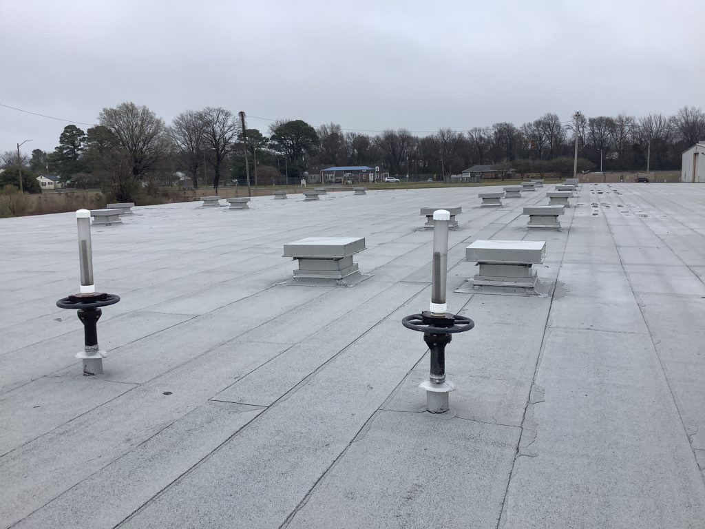
During a renovation, engineers designed a pump suction line that extended 200-ft to the back ends of the reservoir to create a “tank tread” rollover mixing effect. An on-line chloramine analyzer confirms that mixing is sufficient.
Booster Pump Station Operation. For the main booster pump station at Little Creek Joint Expeditionary Base, three elevated water tanks anchor the hydraulic grade line at a maximum of 135-ft (58-psi) at full capacity. To force the tanks to exchange their bowl volumes, the main booster station pressure settings allow the tanks to fluctuate a full 20-ft of water level between pumping cycles. When the pumps are inactive, the elevated tanks feed the distribution system until the tank levels approach the bottom of the bowls. The pumps then repeat the fill sequence.
Because of the available ground level storage, backup diesel generators, and existing municipal bypasses, firefighting capability is not compromised. The tanks exchange their bowl volumes approximately three times daily to minimize residence time.
Cycling Elevated Tanks below the Hydraulic Grade Line. Older installations constructed during World War II typically experience water distribution pressures around 40-psi. As incoming municipal supply pressures increase, the elevated water towers frequently become hydraulically “locked out” of the system. These tanks will not exchange water with the system unless a water main break or a firefighting scenario occurs.
As a simple yet elegant solution at Yorktown Naval Weapons Station, the field engineer installed an altitude valve with a delayed opening feature. An additional pilot valve allows the tank level to drop 15-ft before the valve then reopens to fill the tank.
To force water from the tank into distribution, a small jockey pump operated by a timer simulates a water demand and lowers the tank levels. Once the water level drops by 15-ft from the action of the jockey pump, the altitude valve then reopens to fill the tower.
CORRECTIVE ACTIONS
The Navy employs a variety of corrective actions to reduce water age in installation distribution systems. Determining which actions, if any, to take, however, is dependent on tank size and location, distribution demands, and many other characteristics unique to each system.
• Conducting hydraulic analyses and reviews of fire protection criteria to justify the demolition of redundant water tanks.
• Retrofitting devices and piping configurations of reservoirs to promote more complete
mixing.
• Installing specialty altitude valves to force tank turnover.
• Converting high fire demand areas into non-potable water grids.
• Securing more municipal water feeds to diminish military requirements for storage.
• Installing automated flushing devices to reduce water age.
• Conducting field sampling of total chlorine, ammonia, nitrite, heterotrophic plate counts to
better understand how disinfectants auto-decompose within the water system.
Conversion to Non-Potable Grids and Dual Water Systems. Where fire flow requirements far outweigh any domestic demand, establishing a non-potable fire protection grid is a viable alternative. At an isolated ammunition storage area located at Norfolk Naval Station, water quality suffered with respect to decreased disinfectant residuals, increased disinfectant byproduct levels, and chronic red water complaints. A 20,000-ft distribution system served less than 25 people; weekly hydrant flushing schedules consumed manpower without significantly improving the water quality.
For this scenario, the field engineer designed a “right sized” domestic water system for consumption and building needs. The entire new system was less than 10 percent the size of the existing grid with respect to the pipe footage. To provide fire protection, the original distribution grid was converted to a non-potable fire- fighting grid isolated by new backflow preventers at the incoming mains. Flushing program volumes dropped by 50,000-gal/week. Water quality became a non-issue as evidenced by bacteriological sampling and disinfectant residual monitoring.
CUSTOM SOLUTIONS
Naval installations have unique characteristics that degrade water quality when compared to municipal distribution systems. However, the Navy has successfully dealt with these challenges by using multiple design and operational approaches to manage systems, and taken into consideration unique site characteristics and requirements.
Each installation water distribution system provides opportunities for water quality improvement. Individual systems require different approaches based on tank geometry, location, hydraulic demand patterns, firefighting requirements, and the general building development densities. Determining the best course of action based on the unique characteristics of each system allows for the Navy to preserve water quality in the most effective and efficient manner.
Jeremy Jones, Ph.D., P.E., is Field Engineer, Utilities &Energy management, NAVFAC Mid-Atlantic; jeremy.b.jones1.civ@us.navy.mil.
More News from TME
-
Assessing Mobile Nuclear Reactor Usage in the Pacific
A research team at the Air Force Institute of Technology carried out a lifecycle assessment of the environmental impacts, operational viability, and logistical considerations of mobile nuclear reactors in the Indo-Pacific. -
TME March-April 2025
The March-April 2025 issue of TME features articles on energy security and energy resilience, an inside look at Exercise KEEN SWORD 2025, and a leader profile of Brig. Gen. Patrick Miller, P.E., F.SAME, USAF, Commander of the Air Force Civil Engineer Center. -
Nexus of Sea-Level-Rise, Groundwater, and Stormwater Flooding
Join us for a compelling webinar to learn more about recent efforts in understanding compound flooding from sea level rise, intense rainfall and groundwater rise in the San Francisco Bay. Attendees will hear from experts who will bring in their individual perspectives for adapting to and managing this growing challenge.